Difference between revisions of "Reddy Update"
From IntRoLab
(→Arm Improvements) |
|||
| Line 27: | Line 27: | ||
** Temperature detector. A signal will be sent to the motor controller if the motor temperature is higher than 60 degrees celcius. Analog temperature value is also available. | ** Temperature detector. A signal will be sent to the motor controller if the motor temperature is higher than 60 degrees celcius. Analog temperature value is also available. | ||
** Potentiometer feedback. | ** Potentiometer feedback. | ||
| − | ** Motor power connection | + | ** Motor power connection. |
* Design a new PCB with support to 4 motors | * Design a new PCB with support to 4 motors | ||
* Communicate with the CAN bus already available on Reddy | * Communicate with the CAN bus already available on Reddy | ||
Revision as of 14:02, 28 July 2009
Contents
Schedule
| Week 31, July 27 - August 1 |
|
| Week 32, August 3 - August 9 |
|
| Week 33, August 10 - August 15 |
|
Arm Improvements
To have better control of the arm (and neck) motors, we did the following :
- Change the Motor PCB to support
- Temperature detector. A signal will be sent to the motor controller if the motor temperature is higher than 60 degrees celcius. Analog temperature value is also available.
- Potentiometer feedback.
- Motor power connection.
- Design a new PCB with support to 4 motors
- Communicate with the CAN bus already available on Reddy
- Allow position feedback from the RS-232 interface
- Create a tuning GUI for easier setup of the robot controllers
Motor PCB
Motor Controllers
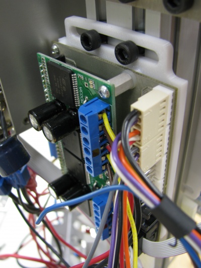
- A new motor drive that can connect up to 4 motors have been designed.
- A new adjustable bracket for fixing the drive to the side of the robot have been designed.
- We installed to motor controllers (one on each side) to allow the modification of 8 motors.
Cabling Improvements
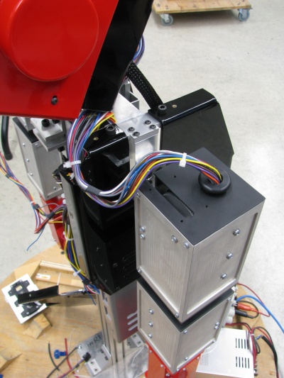
- Cables are now better organized
- Added connectors inside the arm to disconnect motors easily for repairs
- Signals are color coded as follow
- Red
- Green
- (TODO ADD DOCUMENTATION)
Head Improvements
File:ReddyGravityCompensation.jpg
Motor controllers for head movement (YES-NO)
- Same motor controllers were used for the neck to add overheating protection and better feedback / control
Tuning the motor controller
A GUI was created to facilitate motor tuning.
RS-232 protocol enhancements
CAN command added
Future Improvements
- Single 12V power supply could be useful for direct connection to Pioneer robots. A 12V-->8.5V DC-DC (100W) converter is required for this operation. This item can be ordered at Vicor. 8.5V batteries would then be useless.


