Difference between revisions of "Reddy Update"
From IntRoLab
(→Motor Controller Variables) |
(→Motor Controller Variables) |
||
| Line 151: | Line 151: | ||
== Motor Controller Variables == | == Motor Controller Variables == | ||
| + | |||
| + | <pre> | ||
| + | typedef struct _SharedVariables | ||
| + | { | ||
| + | union { | ||
| + | struct { | ||
| + | unsigned char CtrlMode; | ||
| + | unsigned char CtrlType; | ||
| + | |||
| + | unsigned char SetPointSource; | ||
| + | unsigned char PosMesSource; | ||
| + | |||
| + | |||
| + | unsigned short ErrorCode; | ||
| + | |||
| + | short SetPoint; | ||
| + | short SetPointMax; //Maximum SetPoint | ||
| + | short SetPointMin; //Minimum SetPoint | ||
| + | |||
| + | short Current; | ||
| + | short CurrentOffset; | ||
| + | |||
| + | short ADCValue; | ||
| + | short ADCOffset; | ||
| + | |||
| + | short ICValue; | ||
| + | short ICOffset; | ||
| + | |||
| + | |||
| + | short ThermalState; | ||
| + | |||
| + | //CONTROL VARIABLES | ||
| + | short Speed;//16 bit speed | ||
| + | short Position; //16 bits position | ||
| + | short Acceleration; | ||
| + | |||
| + | //PID REF AND MES POINT | ||
| + | short RefPoint; | ||
| + | short MesPoint; | ||
| + | |||
| + | float pid_kp; | ||
| + | float pid_ki; | ||
| + | float pid_kd; | ||
| + | float pid_error; | ||
| + | float pid_error_accum; | ||
| + | float pid_error_derivative; | ||
| + | float pid_error_accum_max; //PID I value max limit (abs) | ||
| + | |||
| + | |||
| + | short PIDOut; | ||
| + | |||
| + | //RAM LOC7 (PID + TRAPZ VARIABLES) | ||
| + | |||
| + | short SpeedMax; //for Trapz | ||
| + | short AccelerationStep; //for Trapz, Speed | ||
| + | |||
| + | |||
| + | //RAM LOC8 (TRAPZ VARIABLES) | ||
| + | short InitPoint; //for Trapz | ||
| + | short DestPoint; //for Trapz | ||
| + | short NextPoint; //for Trapz | ||
| + | |||
| + | |||
| + | //RAM LOC9 (CURRENT LIMIT) | ||
| + | short CurrentLimit; //unit = mA | ||
| + | short PWM_CurrentLimit; | ||
| + | short PWM_CurrentStep; //PWM increment | ||
| + | unsigned char CurrentLimitActive; | ||
| + | |||
| + | unsigned char EncoderBias; //Setting this to 1 will invert the encoder sign | ||
| + | unsigned char MotorBias; //Setting this to 1 will invert motor polarity | ||
| + | |||
| + | unsigned char padding[3]; | ||
| + | } __attribute__((packed)); | ||
| + | |||
| + | unsigned char m_data[]; | ||
| + | }; | ||
| + | } SharedVariables; | ||
| + | |||
| + | |||
| + | typedef struct _GlobalVariables | ||
| + | { | ||
| + | union { | ||
| + | struct { | ||
| + | |||
| + | //All control variables | ||
| + | SharedVariables m_variables[4]; | ||
| + | |||
| + | //additional (global) variables | ||
| + | unsigned char m_ESTOPEnabled; | ||
| + | unsigned char m_WriteEEPROM; | ||
| + | short m_loopTime; | ||
| + | |||
| + | unsigned char m_padding[4]; | ||
| + | |||
| + | } __attribute__((packed)); | ||
| + | |||
| + | unsigned char m_data[]; | ||
| + | };//union | ||
| + | } GlobalVariables; | ||
| + | |||
| + | </pre> | ||
== Useful Examples == | == Useful Examples == | ||
Revision as of 15:06, 28 July 2009
Contents
Schedule
| Week 31, July 27 - August 1 |
|
| Week 32, August 3 - August 9 |
|
| Week 33, August 10 - August 15 |
|
Arm Improvements
To have better control of the arm (and neck) motors, we did the following :
- Change the Motor PCB to support
- Temperature detector. A signal will be sent to the motor controller if the motor temperature is higher than 60 degrees celcius. Analog temperature value is also available.
- Potentiometer feedback.
- Motor power connection.
- Design a new PCB with support to 4 motors
- Communicate with the CAN bus already available on Reddy
- Allow position feedback from the RS-232 interface
- Create a tuning GUI for easier setup of the robot controllers
Motor PCB
Motor Controllers
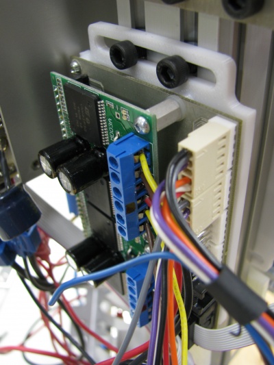
- A new motor drive that can connect up to 4 motors have been designed.
- A new adjustable bracket for fixing the drive to the side of the robot have been designed.
- We installed two motor controllers (one on each side) to allow the modification of 8 motors. Motors modified are :
- Arm-elbow (x2)
- Arm-shoulder (x2)
- Arm-updown (x2)
- Neck-YES (x1)
- Neck-NO (x1)
Cabling Improvements
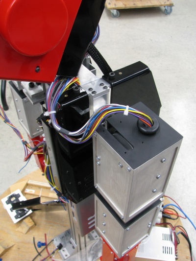
- Cables are now better organized
- Added connectors inside the arm to disconnect motors easily for repairs
- Signals are color coded as follow (TODO ADD DOCUMENTATION)
- Red
- Green
- Black
- Yellow
- Purple
- Gray
- White
- Blue
Head Improvements
File:ReddyGravityCompensation.jpg
Motor controllers for head movement (YES-NO)
- Same motor controllers were used for the neck to add overheating protection and better feedback / control
- Internal servo potentiometers were used for position control.
Tuning the motor controller
A GUI was created to facilitate motor tuning.
RS-232 protocol enhancements
- We added a CAN command to the RS-232 robot interface to allow direct communication with the motor controllers. The RS-232 robot interface now acts as a RS-232 to CAN bridge and bidirectional communication is now possible. This will allow feedback from the motor controllers (current, position, speed, etc.)
(RS-232 CAN COMMAND) <------------------------> (MOTOR DRIVE CAN INTERFACE)
CAN command format for RS-232 communication
Serial messages containing CAN commands will have the following stucture :
| HEADER | CAN_MSG_PRI_MSB_CMD | CAN_MSG_TYPE | CAN_MSG_BOOT_RTR_LENGTH | CAN_MSG_CMD | CAN_MSG_DEST | CAN_MSG_DATA |
| (3 bytes) | (1 byte) | (1 byte) | (1 byte) | (1 byte) | (1 byte) | (8 bytes) |
|
|
|
|
if (MSG_TYPE == REQUEST)
endif if (MSG_TYPE == SENSOR_HIGH_PRIORITY)
endif |
|
|
Note: It is not essential to understand the structure of the CAN messages. Souce code will be provided to format the data correctly.
Motor Controller Variables
typedef struct _SharedVariables
	{
		union {
			struct {
				unsigned char CtrlMode;
				unsigned char CtrlType;

				unsigned char SetPointSource;
				unsigned char PosMesSource;


				unsigned short ErrorCode;

				short SetPoint;
				short SetPointMax; //Maximum SetPoint
				short SetPointMin; //Minimum SetPoint

				short Current;
				short CurrentOffset;

				short ADCValue;
				short ADCOffset;

				short ICValue;
				short ICOffset;


				short ThermalState;

				//CONTROL VARIABLES
				short Speed;//16 bit speed
				short Position; //16 bits position
				short Acceleration;

				//PID REF AND MES POINT
				short RefPoint;
				short MesPoint;

				float pid_kp;
				float pid_ki;
				float pid_kd;
				float pid_error;
				float pid_error_accum;
				float pid_error_derivative;
				float pid_error_accum_max; //PID I value max limit (abs)


				short PIDOut;

				//RAM LOC7 (PID + TRAPZ VARIABLES)

				short SpeedMax; //for Trapz
				short AccelerationStep; //for Trapz, Speed


				//RAM LOC8 (TRAPZ VARIABLES)
				short InitPoint; //for Trapz
				short DestPoint; //for Trapz
				short NextPoint; //for Trapz


				//RAM LOC9 (CURRENT LIMIT)
				short CurrentLimit; //unit = mA
				short PWM_CurrentLimit;
				short PWM_CurrentStep; //PWM increment
				unsigned char CurrentLimitActive;

				unsigned char EncoderBias; //Setting this to 1 will invert the encoder sign
				unsigned char MotorBias; //Setting this to 1 will invert motor polarity

				unsigned char padding[3];
			} __attribute__((packed));

			unsigned char m_data[];
		};
	} SharedVariables;


typedef struct _GlobalVariables
	{
		union {
			struct {

				//All control variables
				SharedVariables m_variables[4];

				//additional (global) variables
				unsigned char m_ESTOPEnabled;
				unsigned char m_WriteEEPROM;
				short m_loopTime;

				unsigned char m_padding[4];

			} __attribute__((packed));

			unsigned char m_data[];
		};//union
	} GlobalVariables;
Useful Examples
Read all motor positions from the motor controller
Write the SetPoint of motor [0-3]
Future Improvements
- Single 12V power supply could be useful for direct connection to Pioneer robots. A 12V-->8.5V DC-DC (100W) converter is required for this operation. This item can be ordered at Vicor. 8.5V batteries would then be useless.


