Difference between revisions of "Reddy Update"
(→Future Improvements) |
(→Additional Notes) |
||
| Line 432: | Line 432: | ||
* Single 12V power supply could be useful for direct connection to Pioneer robots. A 12V-->8.5V DC-DC (100W) converter is required for this operation. This item can be ordered at [http://www.vicr.com/ Vicor]. 8.5V batteries would then be useless. | * Single 12V power supply could be useful for direct connection to Pioneer robots. A 12V-->8.5V DC-DC (100W) converter is required for this operation. This item can be ordered at [http://www.vicr.com/ Vicor]. 8.5V batteries would then be useless. | ||
| − | + | ||
= Documents = | = Documents = | ||
[[File:MotorControllerTuningWin32.zip]] | [[File:MotorControllerTuningWin32.zip]] | ||
Revision as of 19:28, 28 July 2009
Contents
Schedule
| Week 31, July 27 - August 1 |
|
| Week 32, August 3 - August 9 |
|
| Week 33, August 10 - August 15 |
|
Arm Improvements
To have better control of the arm (and neck) motors, we did the following :
- Change the Motor PCB to support
- Temperature detector. A signal will be sent to the motor controller if the motor temperature is higher than 60 degrees celcius. Analog temperature value is also available.
- Potentiometer feedback.
- Motor power connection.
- Design a new PCB with support to 4 motors
- Communicate with the CAN bus already available on Reddy
- Allow position feedback from the RS-232 interface
- Create a tuning GUI for easier setup of the robot controllers
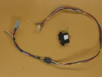
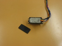
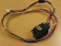
Motor PCB
|
|
|
| Cable + Servo PCB | Servo PCB installed in housing | Final servo + cable + connector |
Motor Controllers
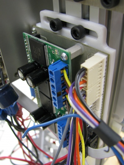
- A new motor drive that can connect up to 4 motors have been designed.
- A new adjustable bracket for fixing the drive to the side of the robot have been designed.
- We installed two motor controllers (one on each side) to allow the modification of 8 motors. Motors modified are :
- Arm-Elbow (x2)
- Arm-Shoulder-Yaw (x2)
- Arm-Shoulder-Pitch (x2)
- Neck-Yaw (x1)
- Neck-Pitch (x1)
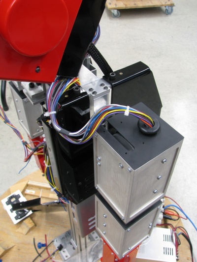
Cabling Improvements
- Cables are now better organized
- Added connectors inside the arm to disconnect motors easily for repairs
(TODO ADD DOCUMENTATION FOR CABLING)
- Signals are color coded as follow
- Red
- Green
- Black
- Yellow
- Purple
- Gray
- White
- Blue
Head Improvements
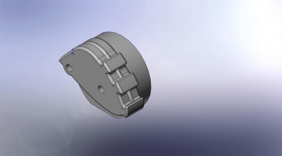
We added gravity compensation for the head to minimize power required for motors.
TODO Add description here
Motor controllers for head movement (Yaw + Pitch)
- Same motor controllers were used for the neck to add overheating protection and better feedback / control
- Internal servo potentiometers were used for position control.
Tuning the motor controller
A GUI was created to facilitate motor tuning.
Warning! This GUI is intended for Engineers at IntRoLab and changing control values can lead to indesirable effects. Assistance will be required before changing controller values.
[[Image::ReddyTuningGUI.jpg|600px|center]]
RS-232 protocol enhancements
- We added a CAN command to the RS-232 robot interface to allow direct communication with the motor controllers. The RS-232 robot interface now acts as a RS-232 to CAN bridge and bidirectional communication is now possible. This will allow feedback from the motor controllers (current, position, speed, etc.)
(RS-232 CAN COMMAND) <------------------------> (MOTOR DRIVE CAN INTERFACE)
CAN command format for RS-232 communication
Serial messages containing CAN commands will have the following stucture :
| HEADER | CAN_MSG_PRI_MSB_CMD | CAN_MSG_TYPE | CAN_MSG_BOOT_RTR_LENGTH | CAN_MSG_CMD | CAN_MSG_DEST | CAN_MSG_DATA |
| (3 bytes) | (1 byte) | (1 byte) | (1 byte) | (1 byte) | (1 byte) | (8 bytes) |
|
|
|
|
if (MSG_TYPE == REQUEST)
endif if (MSG_TYPE == SENSOR_HIGH_PRIORITY)
endif |
|
|
Note: It is not essential to understand the structure of the CAN messages. Souce code will be provided to format the data correctly.
Motor Controller Variables
Motor controller internal variables can be represented like this :
typedef struct _SharedVariables
	{
		union {
			struct {
				unsigned char CtrlMode;
				unsigned char CtrlType;
				unsigned char SetPointSource;
				unsigned char PosMesSource;
				unsigned short ErrorCode;
				short SetPoint;
				short SetPointMax; //Maximum SetPoint
				short SetPointMin; //Minimum SetPoint
				short Current;
				short CurrentOffset;
				short ADCValue;
				short ADCOffset;
				short ICValue;
				short ICOffset;
				short ThermalState;
				//CONTROL VARIABLES
				short Speed;//16 bit speed
				short Position; //16 bits position
				short Acceleration;
				//PID REF AND MES POINT
				short RefPoint;
				short MesPoint;
				float pid_kp;
				float pid_ki;
				float pid_kd;
				float pid_error;
				float pid_error_accum;
				float pid_error_derivative;
				float pid_error_accum_max; //PID I value max limit (abs)
				short PIDOut;
				short SpeedMax; //for Trapz
				short AccelerationStep; //for Trapz, Speed
				short InitPoint; //for Trapz
				short DestPoint; //for Trapz
				short NextPoint; //for Trapz
				short CurrentLimit; //unit = mA
				short PWM_CurrentLimit;
				short PWM_CurrentStep; //PWM increment
				unsigned char CurrentLimitActive;
				unsigned char EncoderBias; //Setting this to 1 will invert the encoder sign
				unsigned char MotorBias; //Setting this to 1 will invert motor polarity
				unsigned char padding[3];
			} __attribute__((packed));

			unsigned char m_data[];
		};
	} SharedVariables;


typedef struct _GlobalVariables
	{
		union {
			struct {

				//All control variables
				SharedVariables m_variables[4];

				//additional (global) variables
				unsigned char m_ESTOPEnabled;
				unsigned char m_WriteEEPROM;
				short m_loopTime;
				unsigned char m_padding[4];

			} __attribute__((packed));

			unsigned char m_data[];
		};//union
	} GlobalVariables;
Notes :
- Understanding the structure of the controller is not required for normal operation.
- The structure GlobalVariables represents the memory organization of the motor controller. You can see that it contains control variables (SharedVariables structure) for 4 motor axis.
- Using the CAN protocol, we can access each variable and read/write its value.
- The GUI was designed for easy tuning of those variables by our engineers.
New Joints Configuration
TODO : Update Servo Ranges
| Motor controller id=0x01 | Motor controller id=0x02 |
|
|
Useful Examples
Those examples will probably contain all you will need to do to operate the robot.
Read all positions from the motor controller
The computer sends this to the RS-232 server (Remote request) :
| HEADER | CAN_MSG_PRI_MSB_CMD | CAN_MSG_TYPE | CAN_MSG_BOOT_RTR_LENGTH | CAN_MSG_CMD | CAN_MSG_DEST | CAN_MSG_DATA |
| (3 bytes) | (1 byte) | (1 byte) | (1 byte) | (1 byte) | (1 byte) | (8 bytes) |
|
|
|
|
|
|
|
Serial Message Sent:
- serial_message[0] = 'c'
- serial_message[1] = 'a'
- serial_message[2] = 'n'
- serial_message[3] = 0x00
- serial_message[4] = 0x04
- serial_message[5] = 0x78
- serial_message[6] = 0x90
- serial_message[7] = 0x01 or 0x02
- serial_message[8] = (ignored)
- serial_message[9] = (ignored)
- serial_message[10] = (ignored)
- serial_message[11] = (ignored)
- serial_message[12] = (ignored)
- serial_message[13] = (ignored)
- serial_message[14] = (ignored)
- serial_message[15] = (ignored)
The RS-232 server responds (response to remote request):
| HEADER | CAN_MSG_PRI_MSB_CMD | CAN_MSG_TYPE | CAN_MSG_BOOT_RTR_LENGTH | CAN_MSG_CMD | CAN_MSG_DEST | CAN_MSG_DATA |
| (3 bytes) | (1 byte) | (1 byte) | (1 byte) | (1 byte) | (1 byte) | (8 bytes) |
|
|
|
|
|
|
|
Serial Message Received :
- serial_message[0] = 'c'
- serial_message[1] = 'a'
- serial_message[2] = 'n'
- serial_message[3] = 0x00
- serial_message[4] = 0x04
- serial_message[5] = 0x68
- serial_message[6] = 0x90
- serial_message[7] = 0x01 or 0x02
- serial_message[8] = Motor 0 Position LSB
- serial_message[9] = Motor 0 Position MSB
- serial_message[10] = Motor 1 Position LSB
- serial_message[11] = Motor 1 Position MSB
- serial_message[12] = Motor 2 Position LSB
- serial_message[13] = Motor 2 Position MSB
- serial_message[14] = Motor 3 Position LSB
- serial_message[15] = Motor 3 Position MSB
Read all setpoints from the motor controller
Read all currents from the motor controller
Write the SetPoint of motor [0-3]
Additional Notes
- Single 12V power supply could be useful for direct connection to Pioneer robots. A 12V-->8.5V DC-DC (100W) converter is required for this operation. This item can be ordered at Vicor. 8.5V batteries would then be useless.

